TouchDesigner: map two projectors onto two angled surfaces with projectorBlend, Stoner, and kantanMapper

Translated from the original Traditional Chinese version.

Summary

When two projectors cover two surfaces that meet at an angle, you can put the seam on the crease between the surfaces and skip edge blending. projectorBlend only splits the image, and each projector then gets one Stoner to correct fabric sag and one kantanMapper to align the four corners.

Table of contents

When two projectors have to cover two surfaces that meet at an angle, I put the seam directly on the crease where the surfaces meet. There is no edge blending, and the images of the two projectors do not need to overlap. In TouchDesigner (TD below), projectorBlend only lines up the images of the two projectors, and two Crop TOPs cut that into a left half and a right half. Each projector then gets a Stoner to correct fabric sag, followed by a kantanMapper to align the four corners. All three components are in the TD Palette, and the whole chain looks like this:
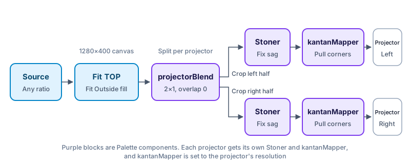
The source image goes through a Fit TOP set to Fit Outside to fill a 1280×400 canvas. projectorBlend with 2×1 and overlap 0 processes it, and a Crop takes the left and right halves. Each half goes through Stoner to fix sag and kantanMapper to pull the four corners, and then to the left and right projector
The screenshots in this article come from a simulated setup that I rebuilt in TD 2025.32050 with td-cli. Two fabric surfaces of 2.4 m × 1.5 m meet at a 120° angle, the center sags back by 10 cm, and two projectors sit on the floor pointing up at 40°. TOPs in the Non-Commercial version are limited to 1280 px, so the simulation shrinks each projector to 640×400. A production setup needs a Commercial license to run the projectors at their native resolution.

Canvas and resolution

The only thing I calculate myself is the resolution. The canvas is the size of the two projectors side by side, and kantanMapper uses the size of a single projector. For two 1920×1200 projectors side by side, set the output resolution of the Fit TOP to 3840×1200, and set the resolution of each projector in projectorBlend and the Resolution of kantanMapper to 1920×1200.

The aspect ratio of the source image is usually different from the canvas. When the image has no content that has to line up with a physical object, I set the Fit parameter of the Fit TOP to Fit Outside, so the image is enlarged proportionally until it fills the canvas, and the extra at the top and bottom or at the sides is cropped away. On the left is a 4:3 test image, and on the right is how it looks after filling a 1280×400 canvas:
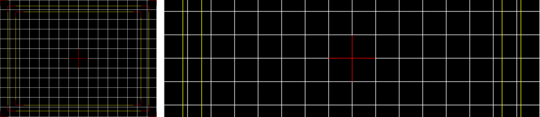
On the left, a 4:3 grid test image with yellow and red outlines. On the right, the same image enlarged proportionally to a 1280×400 canvas, with the top and bottom cropped away so only the middle band of the grid remains, the yellow vertical lines at the left and right edges, and a red cross in the center
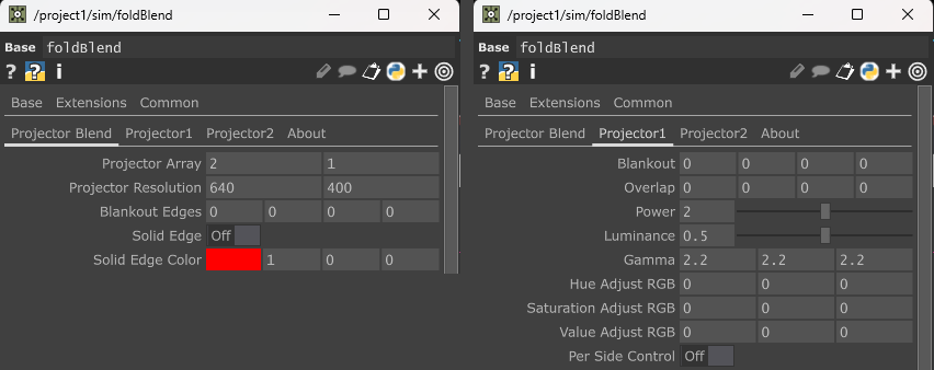
Set the array of projectorBlend to 2×1 and overlap to 0. The array and the resolution of each projector are on the Projector Blend page, and overlap is on the pages of each projector, Projector1 and Projector2. Its output is still one image with the two projector images side by side, so connect two Crop TOPs after it, one to cut out the left half for the left projector and one for the right half for the right projector.

Two pages of the projectorBlend parameter window. On the left, the Projector Blend page has Projector Array set to 2 and 1 and Projector Resolution set to 640 and 400. On the right, the Projector1 page has all four Overlap fields set to 0
The official description says the input is stretched to the array size. In TD 2025.32050, what I saw was that when the input size is wrong, the image is enlarged proportionally and the edges are cut off. You cannot see this with a grayscale test image, only with a grid image.

One kantanMapper per projector to align the four corners

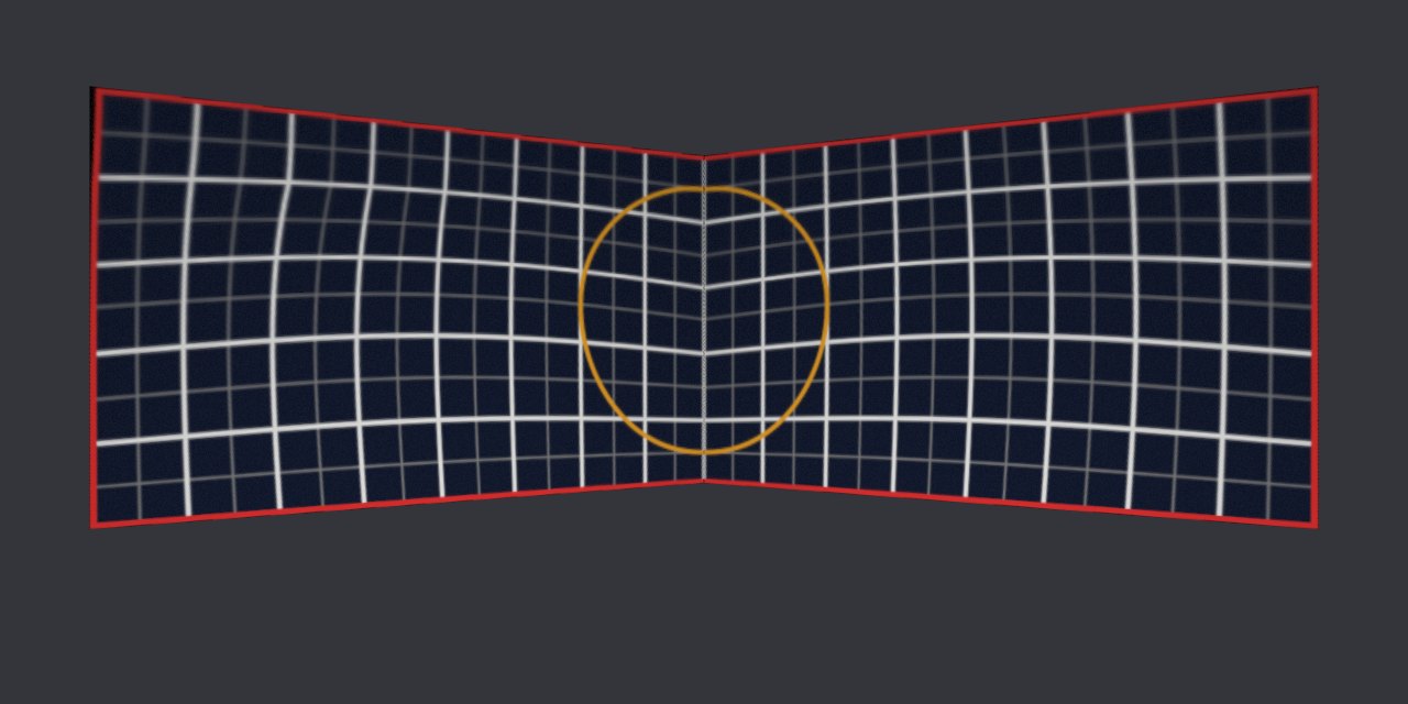
kantanMapper is a component for aligning by drawing shapes on the projected image and dragging their vertices directly. Four-corner correction can only pull the image inward, so the projection area of each projector has to cover the surface it is responsible for. The image below shows the two projectors just after setup, each outputting its own half image directly. The two projectors cross in the middle, each image goes past the crease onto the other surface, and the orange ring that straddles the seam is split into two pieces:
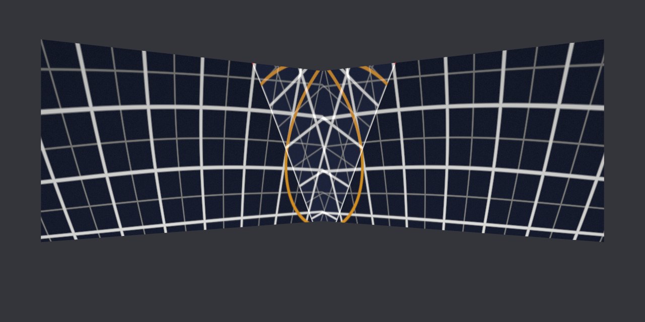
The simulated image before correction. Two surfaces meet at an angle, and the grids of the left and right projectors cross in the middle and land on each other’s surface. The orange ring is split into two arcs that do not line up
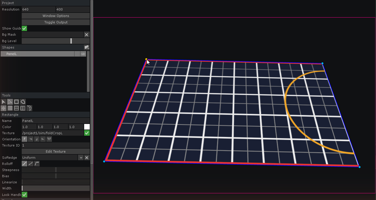
Put one kantanMapper on each projector and draw a rectangle inside it, using the Stoner of that projector as its texture. Until you drag any point in Stoner, what it sends out is the half image cut by projectorBlend, so you can pull the four corners first. Select the rectangle and switch to the vertex tool, and the four corners show points you can drag. Look at the surface and pull them to the four corners of this surface:

The edit window of the left kantanMapper. On the left side, Resolution is 640 and 400 and the Shapes list has one rectangle selected. On the right, the rectangle has been pulled into a trapezoid with a dot at each of the four corners, and the mouse is over the top left point
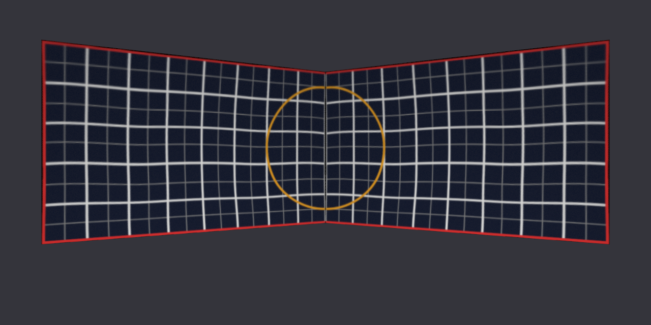
After both are pulled, the seam sits on the crease and the orange ring joins into one circle:

The simulated image after kantanMapper aligned the four corners. The red outline fits the edges of the two surfaces, and the orange ring joins into a full circle on both sides of the crease, but the grid lines in the middle of the surface are slightly curved
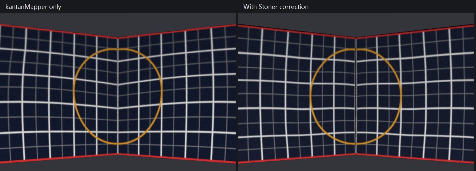
The edges and the seam are now correct, but the grid lines in the middle of the surface are still curved. Pulling only four corner points gives you a perspective correction only. The curve caused by the fabric sagging backward is for Stoner to fix.

Fix fabric sag with Stoner

Once the fabric is hung, its middle sags backward, and the grid projected on it curves.

The rectangle in kantanMapper can also be cut into a mesh to fix local areas, but I split the work between the two components. kantanMapper puts the image at the right position on the surface, and it is also where I draw masks when I need them. Stoner only corrects the shape of the image.

Place Stoner before kantanMapper, connected directly to the left or right half cut out of projectorBlend. That way the image you see in the Stoner window is the original undistorted image, and by looking at the projection you know which area to drag in which direction. If you place it after kantanMapper, the image in the window has already been pulled into a trapezoid, and dragging points while looking at it, you cannot move the content to where it belongs on the surface.

Switch Stoner to Grid Warp to drag grid points and push or pull the image locally. Click a grid point and the handles of a Bezier curve appear, and dragging a handle adjusts the curvature of the grid lines around that point:
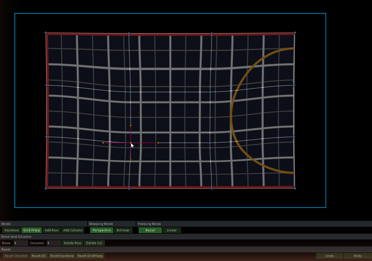
The Grid Warp window of the left Stoner. On the flat half image there are 4×4 grid points. A point at the lower left is selected with four Bezier handles extending up, down, left, and right, and the mouse is over this point. Mode at the bottom is set to Grid Warp, and Rows and Columns are both 4
In practice I use the default 4×4 grid. I look at the projected image to find the areas where the grid lines are distorted, then drag the grid points in those areas until the image looks normal again. On the left is only kantanMapper, and on the right is the result with the Stoner correction added:

A comparison near the seam. On the left, with only kantanMapper, the horizontal grid lines inside the orange ring curve downward. On the right, with the Stoner correction, the lines are straight again
If the 4×4 grid points are too sparse to pull back the distortion in some area, increase Rows and Columns and drag the points again. Changing Rows or Columns with a number resets the whole grid, so every point you dragged before is cleared.

After the correction, if content from the other side of the image shows up next to the seam, it is because Stoner wraps the part beyond the image edge around to the opposite side by default. Go inside Stoner and set Color Map Extend U/V of render/constant1 and the sampler Extend U/V of render/phong1GLSL to Zero, and it disappears.

Summary

The image below shows how the setup looks after both projectors are corrected, seen from the front left, the front, and the front right. The gray blocks on the floor are the two projectors, which sit in front of the surfaces and cross their projections upward:
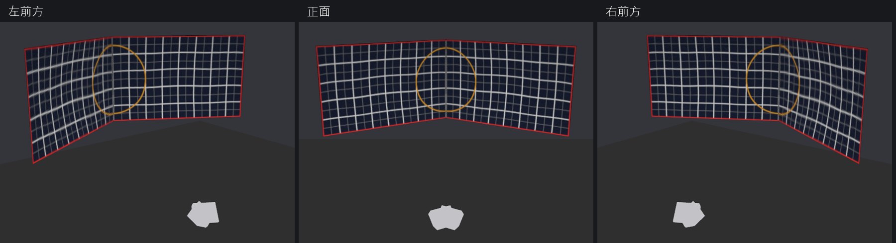
The corrected simulated scene seen from the front left, the front, and the front right, with two surfaces that meet at an angle. The grid lines are continuous on both sides of the crease, the orange ring joins into a full circle, and gray blocks on the floor in front of the surfaces stand for the two projectors
When the seam sits on the crease you do not need edge blending, and the only numbers to work out are the resolution of the canvas and of a single projector. After kantanMapper aligns the four corners, Stoner fixes the remaining fabric sag.

Stoner also has a second output besides the corrected image, a displacement map. The official documentation suggests that once you have finished adjusting and kept this displacement map, you remove Stoner from the project and use a Remap TOP to read the displacement map and warp the image, which performs much better. Connect the image to warp to the first input of the Remap TOP, and the displacement map to the second input. For a live show, you can swap out the two Stoners this way.

Where to go next

PreviousInstall and use the official ComfyUI MCP: let Claude Code run workflows to generate imagesAINextClaude Code deny rules miss git push --force: how Bash rules match commands, and rules that workAI
Ted Liou

Ted Liou

Software engineer writing about Unity and AI development. Available for consulting.